
Showing posts with label Chemicals. Show all posts
Showing posts with label Chemicals. Show all posts


Sulfuric acid production process flow sheet
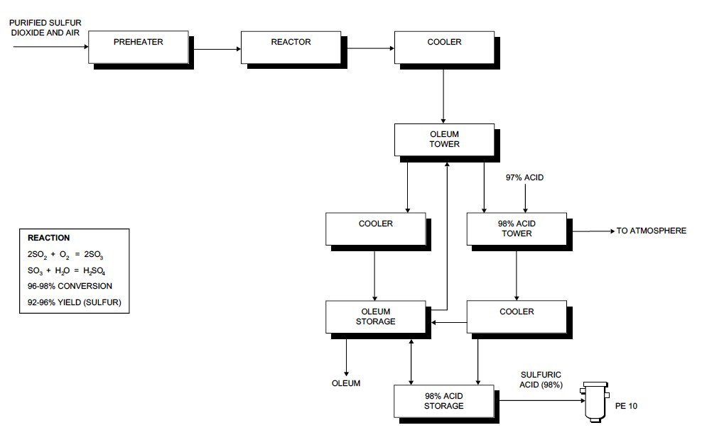
The catalytic reaction generates a lot of heat and is reversible. The catalyst tower is, therefore, arranged with
Ultra Violet fly repellant making process
Raw Materials
The main raw materials used to produce ultra violet fly repellent plant are metal sheets, roads, weld mesh, wire ropes, ballast, transformer, ultra violet tube, and other electrical components.
The manufacturing process of the device can be briefly described as follows. First, sheet metal is cut in standard shapes in order to cover and support the various electrical components. This structure is then painted. A special gird is also to be fabricated from steel wire rod and nickel (chrome plated). Then a suitable protective guard fabricated from weld mesh is provided in order to prevent accidental contact with the grid.
Various electrical components like
Acetylene Production Process description
Acetylene is an organic compound produced from the exothermic reaction of calcium carbide and water. Either as liquid or gas, it is highly explosive since it is an endothermic compound and decomposes into the elements carbon and hydrogen. Acetylene is used as raw material to produce different chemicals such as vinyl chloride (a chemical used to produce PVC), 1, 4-Butanediol, vinyl acetate, etc. In addition, it is used as fuel in gas welding. Acetylene with oxygen produces high temperature flame (3500 o C) which is used to cut and weld different metallic products.
Raw Materials
The major raw materials of the production of acetylene are calcium carbide and water. Other auxiliary materials are nitrogen, iron oxide and silica gel.
The major raw materials of the production of acetylene are calcium carbide and water. Other auxiliary materials are nitrogen, iron oxide and silica gel.
The size of calcium carbide shall first be reduced to fine powder by pulverizer. The pulverized carbide is then added though a gas tight hopper-valve arrangement to the acetylene gas generator in which the quantity of water used is sufficient to discharge the calcium hydroxide as lime slurry containing 85-90% water. The temperature is kept below 90oc and 2 atm. the gas generator.
The impure acetylene (C2H2) from the generator is scrubbed with water. The continuous supply of cooling water in to the scrubber is also used as a source of water for the reaction with carbide. After the scrubber, the gas is purified and dried with iron-oxide and silica gel.
The production process is environmental friendly. The by product slaked lime is used for construction purpose and PH adjustment in industry.
Main Equipments
Main Equipments
- Water tank
- Carbide feed mechanism
- Carbide buffer
- Acetylene generator
- Pulverizer Scrubber
- Purifier
- Nitrogen cylinders
- Pumps
Glass Manufacturing process: Soda lime
Most glass articles are manufactured by a process in which raw materials are concerted at high temperature to a homogeneous melt that is then formed into articles. The manufacturing process starts with:
Preparation of raw material
The efficiency of the melting operation and the uniformity and quality of the glass product are very often determined in the mix house. The method by which the batch is mixed depends on the types of the glass rather than on the size of the tank. High SiO2 glasses (soda lime, borosilicate, aluminosilicate) tend to be batch mixed in pan type mixer. The mixture is first dry blended and the small amount of liquid are coming into vogue for several reasons;
- A wet batch prevents dusting, controls air pollution, and ensures homogeneity, and therefore, increase melting efficiency and glass quality. (Chemical Technology, volume 11)
The manufacturing procedures may be divided into four major phases: (Shreve's, 1980)
- Melting
- Shaping or forming
- Annealing, and
- Finishing
Melting: Ideally, when the intimately mixed batch is charged into hot furnace, a series of melting, dissolution, volatilization, and redox reactions take place between the materials in a particular order and at the appropriate temperature. Preheating raises rapidly as possible to the melting temperature where significant reactions occur generally in a distinct change in the flow characteristics of the batch.
Dissolution of the more refractory (high melting material) grains, such as sand, is accelerated by fluxes (lower melting material), e.g. NaCO3.
Example NaCO3+SiO2 Na2Si2O3 occur first at about 550c and a layer is deposited on the silica grains. As the reaction continuous,
NaSiO3+SiO2 Na2Si2O3 occurs at 7000c. Finally at about 7800c, forms a mixture approaching eutectic liquid.
Fining: is the physical and chemical process of removing gas bubbles (seeds, blisters) from the molten glass melt. Gas is evolved during the first stage of melting because of:-
- The decomposition of the carbonates or sulfates
- Air trapped between the grain of the fine grained batch materials
- Water evolved from the hydrated batch materials
- The change in oxidation state of some of the batch materials e.g. red lead.
2Pb3O4 6PbO + O2
Melt homogenization followed by cooling to working temperatures completes the melting process.
Melting Units
Melting units range from small pots furnaces for manual production to large, continuous tanks for rapid machines forming. The largest furnaces are continuous regenerative furnaces that recover waste heat from burned glass. They produce large quantities of quality glass and are either cross or end-fired. Production ranges from less than 150 to 700ton/day. The two ports of an wend port furnace produce a u-shaped flame over the glass that enters the exhausts from the back well, where as cross- firing from side to side allows more even heating across a larger surface area. Each type of furnace has a melting portion and a conditioning portion which are separated by a refractory bridge well. Furnace designs range from shallow rectangular types to round and vertical.
Feeding system
The two common feeding designs used today are the screw feeder and the reciprocating pusher.
Screw feeder: - delivers the batch from a hopper to the furnace by tube and helical gear drive.
Reciprocating pusher: - forces a layer of the batch from the feed chutes onto the molten glass.
Fuel and efficiency:-natural gas, oil, and electricity are the primary source of energy; propane is as backup reserves in emergencies. Natural gas is the least expensive and most frequently used fuel with heat content ranging from 34-45mJ/m3 (Chemical technology, volume 11)
Glass production process video
Forming: There are for main methods of forming glass:
- Blowing
- Pressing
- Drawing
- Casting
Blowing: -
Deep items such as bottles, jars, or light-bulb envelopes are formed by the use of air pressure either from a pair lunges or an air compressor.
Pressing:- flat item such as dinner ware, optical and sealed beam lenses, filter glasses, and television tube panels are pressed between plunger and a mold most commonly with an automatic rotary press; cost iron, bronze, steel and some special alloys are common mold materials.
A gob of glass is fed into the mold at the first station. The table rotates and a retaining ring and plunger press the article at the next station.
Casting: - is the process of shaping glass by pouring it into a mold.
Annealing:
To reduce strain, it is necessary to anneal all glass objects, whether they are formed by machines or hand-molding methods. Annealing involves two operations.
- Holding a mass of glass above a certain critical temperature long enough to reduce internal strain by plastic flow to less than predetermined maximum.
- Cooling the mass to room temperature slowly enough to hold the strain blow this maximum.
With the forgoing data as basis, engineers are produced continuous annealing equipment, with automatic temperature regulation and controlled circulation, which permits better annealing at a lower cost and with less loss of product.
Finishing:
All types of annealed glass must undergo certain finishing operations which, though relatively simple, are very important. These include cleaning, grinding, polishing, cutting, sand blasting, enameling, grading, and gagging. Although all these are required for every glass object, one or more are almost always necessary. (Shreve's, 1980)
Industrial Oxygen Production Process
The detail production process of producing industrial oxygen is presented as follows. First, air is drawn from atmosphere through Suction Air Filter to prevent dust from getting into the system. The air is then compressed in a four stage Air Compressor. Air Compressor has inter-coolers between stages and an After-Cooler after 4th stage. Then compressed air, cooled in evaporation cooler will enter into a Moisture Separator. After this the air will pass through an additional cooler called Chilling Unit. Then the air will pass through Oil Absorber where the Oil Vapor carried over from Air Compressor will be removed.
The air then enters one of the Molecular Sieve Vessels/battery. The moisture and carbon dioxide in the air will be removed in this drier. The dry air is again filtered in a Dust Filter before entry to Cold Box to avoid any dust entry to Cold Box. The compressed air, cooled to about 15 to 20 Co free of moisture and carbon dioxide will enter the Cold Box. It initially passes through a Heat Exchanger where the incoming air will be cooled by the outgoing Oxygen and Nitrogen. The air will be cooled to around 100 Co. The air will then be into two streams. The main air stream will enter Expansion Engine at 40 Kgs./Cm2 and will be expanded to 5 Kgs./Cm2 and 150 to 160 Co the rest of the air will pass through Heat Exchanger to be cooled to about 160 Co by the outgoing Oxygen and Nitrogen. This air will then be expanded by an Expansion Valve to form liquid air. Both the air streams will now enter bottom portion of the Lower Column. Operating pressure of the column is around 40 kg/cm2 under normal operating conditions.
As the air enters the Lower Column, after the Expansion Engine and after Expansion Engine valve, a part of this air condenses into liquid and falls at the bottom of the column. This liquid is about 40% Oxygen and 60% Nitrogen and is usually called the “Rich Liquid” and as Nitrogen is more volatile it rises to top of the lower column where it gets cold from the condenser and become liquefied.
Final separation of the two fractions is achieved in the upper column. Both of the poor liquids are carried into the upper column by two Expansion Valves and the pressure drops in the upper column. The rich liquid enters the middle of the Upper column and as it flows down, Nitrogen evaporates and Oxygen continues as liquid. The Liquid Nitrogen (Poor Liquid) enters the top of the column and as it flows down the column, it comes in contact with any evaporating Oxygen and condenses the same into liquid, while the Nitrogen itself becomes a Gas as it is more volatile.
This process takes place in each Gas as it is more volatile. This process takes place in each tray. The entire gaseous Nitrogen is piped out from the top of the column through Heat Exchangers. Similarly the Liquid Oxygen at the bottom of the column is carried away to a Liquid Oxygen Pump from which it is compressed and again passed through the Heat Exchangers into the Gas Cylinders in the cylinder filling station. As the Liquid Oxygen travels through the Heat Exchangers, it evaporates into gaseous oxygen filling the cylinder with gas and giving up its cold to the incoming air. Generally the purity of Oxygen will be 99.5% when the plant is operated exclusively for oxygen production.
The alternative technological option makes use of what is commonly known as the ‘Linde Process”. This method employs an elaborate and complex process which requires highly skilled engineers and workers to separate oxygen from air.
Detergent Manufacturing Process with flowchart
Adapted from Shreves, Chemical process Industries
Main reaction
Alkylbenzene + Oleum -----> Alkylbenzene sulphonate + sulfuric acid
Process steps
Sulfonation-sulfation
The alkylbenzene is introduced continuously into sullfonator with the requisite amount of oleum. The temperature should be maintained about 55C. Fatty tallow alcohol and more oleum are fed into sulfonated mixture.The mixture is then pumped to the sulfater (should also operate arroun50-55C)

Neutralization
The sulfonated –sulfated product is neutralized with NaOH solution under controlled temperature to maintain fluidity of the surfactant slurry. The surfactant slurry is conducted to storage.
The surfactant slurry, sodium tripolyphostphate and most of the miscellaneous additives are introduced into the crutcher. A considerable amount of the water is removed and the paste is thickened by sodium tripolyphostphate hydration reaction.
The mixture is pumped to an upper story where it is sprayed under high pressure into the 24m high spray tower, counter to hot air from the furnace. Dried granules of acceptable shape and size and suitable density are formed. The dried granules are transferred to a upper story by an air life which cools them from 115C and stabilize the granules. They are then separated in a cyclone , screened, perfumed and packed.
Detergent production process video
Detergent production process video
Filter aid production process
The natural discoloring power of filter aids can be greatly increased by an acid treatment which generates the so-called “activated earth”. The acid treatment of diatomaceous earth eliminates alkalis and calcium, reducing the contents of magnesium, iron and aluminum in it. The acid treatment can be carried out by using either sulfuric acid (H2SO4) or hydrochloric acid (HCL). Calcium oxide is used for the neutralization of the spent acid.
The production process of filter aids from diatomaceous earth essentially involves the following operations. The crude material is mixed with water to form a suspension to which sulfuric acid is added. The mixture is then heated by steam in a mixing tank up to a temperature of 40oc and kept at this temperature for about 4 hours. Then the mixture is heated to 180oc for one hour. After cooling the suspension is filtered through a filter press and washed in order to eliminate excess acidity. The cake of the activated earth is then dried through a pneumatic conveyor by hot air (700oc). The product is collected in a depot and then packed. The activated earth is packed in craft paper bags of 50kg. Filling operations are carried out manually. Any leak of sulfuric acid that could be generated will be washed by water and neautralized to a PH of 6-8 so that it will be disposable with out harming the environment.
Laundry soap manufacturing
Production Process
Laundry soap production regarding to this project is batch system. Soap making or the saponification process is done by reacting fatty acids with a caustic alkali, the properties of the resulting soap depending on the mixture of fats used, the kind of caustic alkali and the actual process employed. Caustic soda is most often used but caustic potash, or a mixture of the two, are also suitable. Potash produces a finer product. Sophisticated items such as perfumed bath preparations require prior bleaching and deodorization of the fats to achieve the color, odor and performance features desired in the finished bar.
production regarding to this project is batch system. Soap making or the saponification process is done by reacting fatty acids with a caustic alkali, the properties of the resulting soap depending on the mixture of fats used, the kind of caustic alkali and the actual process employed. Caustic soda is most often used but caustic potash, or a mixture of the two, are also suitable. Potash produces a finer product. Sophisticated items such as perfumed bath preparations require prior bleaching and deodorization of the fats to achieve the color, odor and performance features desired in the finished bar.i) Oil slowly heated in an open pan; concentrated caustic soda solution added, slowly in small quantities at a time, boiling over a period of several hours. The mixture must be boiled under controlled conditions, to ensure completion of the saponification process without over-boiling.
ii) A moderate heat is maintained and each addition of caustic soda solution is allowed to react fully with the oils, before the next addition. Hasty addition of caustic soda solution will result in undesirable graining. If the mass shows signs of separating or graining, further water is added to bring the oil charge to a homogeneous state.
iii) After as much as 5 hours boiling, a fatty layer emerges on top of the mixture. This is mostly half-spent caustic, some of which should be added to the next batch in the pan to speed emulsification. Eventually the soap separates as a loose curd leaving more ½ spent caustic. The mass thickens, gets increasingly transparent and finally assumes a peculiar shiny translucent surface free from froth. If colors are to be added to the soap these should be incorporated before closing the boiling operation.
iv) On settling and cooling, which may take up to 4 days, the soap separates into 3 layers, pure neat soap uppermost, next an impure nigre soap and at the bottom a nigre lye. The pure soap is skimmed off for further processing the nigre soap goes to be re-worked and the lye gets returned to a next boiling batch. Perfumes, if any, may be added after the soap charge in the pan has become cooled a little.
v) Builders and fillers are added and thoroughly crunched in; the soap is then transferred to frames for subsequent cooling and cutting.
in; the soap is then transferred to frames for subsequent cooling and cutting.A valuable by-product of this process is glycerin, which is usually recovered by chemical treatment, followed by evaporation and refining. (Refined glycerin is an important industrial material used in foods, cosmetics, drugs and many other products.)
If the producer requires alternative technology one can employ Semi-Boiled or Cold processes which are economical and simple ways of making soft or potash soaps, requiring low-cost investment in equipment and no sophisticated skills. In addition to the above two alternatives, continuous processes with automated and compact equipment are widely employed to save installation space, consumption of steam and electric power and labor.
Insecticide Aerosol
Production Process
The production process to be employed in the envisaged plant involves the preparation of the insecticide spray and bottling (can filling).
spray and bottling (can filling). The insecticide raw material is blended with synergist and other ingredients such as aromatic essence to a given formulation. The blend is then filtered to remove any impurities. Alternatively, ready blended aerosol concentrate can be bought in and diluted. The can should be inspected on receipt and later air blast cleaned before the filling operation.
and other ingredients such as aromatic essence to a given formulation. The blend is then filtered to remove any impurities. Alternatively, ready blended aerosol concentrate can be bought in and diluted. The can should be inspected on receipt and later air blast cleaned before the filling operation. The product filler and crimper/gaster and mounted on an operating bench which has an integral extraction system. At this level of production, the cans are fed manually into the enclosures of both machines. It is also possible to employ automatic enclosure systems, which produce 12-15 cans a minute. The insecticide solution is pumped from the storage tank to the filling machine where the cans are filled. They are then passed to the crimper/gaster where they are filled with the propellant and sealed tight by fitting an inner stopper and cap.
where they are filled with the propellant and sealed tight by fitting an inner stopper and cap. The propellant is filtered before being pumped into the filler machine fitted with gas detection equipment. Finally the caps are mounted on the cans which are then packed in carton boxes for dispatch after inspection.
is filtered before being pumped into the filler machine fitted with gas detection equipment. Finally the caps are mounted on the cans which are then packed in carton boxes for dispatch after inspection. Citric acid production process
Citric acid can be extracted from the juice of citrus fruits, by fermentation of glucose with the aid of the mold Aspergillus niger and synthetically from acetone or glycerol.

Today, essentially all of the commercial citric acid is produced by fermentation. Processes employed are surface or submerged fermentation by mold (Aspergillus niger) and submerged fermentation by yeast
Carbondioxide production process
Coke is burned under specially designed boilers in carborundum lined furnace. Combustion is controlled by drafts, so that flue gases contain 17-18% carbon dioxide. At the same time steam is generated in the boilers to furnish power for the pumps and compressors and heat for the lye boiler. The hot flue gases, containing oxygen, carbon monoxide, nitrogen, dust and some sulphur and organic compounds, in addition to 18% carbon dioxide are passed through a heat exchanger and economizer. Here the temperature of the gases is reduced and the excess heat is taken up by the counter currently flowing strong lye. The gases are scrubbed in limestone packed towers with water from the coolers to remove sulphur dioxide and dust and to reduce the temperature to about 38oC. The dilute carbon dioxide is then fed into the bottom of the coke filled absorption towers where it passes counter current to an aqueous solution of sodium carbonate called weak lye. After absorbing the carbon dioxide, the solution of bicarbonate, known as strong lye, is pumped through heat exchangers, where the solution is heated before entry into the lye boiler. The absorbers remove all but about 9% of the carbon dioxide in flue gas, which is then released to the atmosphere.
The preheated solution of sodium bicarbonate is heated with exhaust steam (from the compressors) in the lye boilers. Here, at a temperature of about 118oC, the bicarbonate is decomposed into sodium carbonate (weak lye), which is returned through heat exchanger to the absorbers for reuse. The liberated gas, consisting of 99.8% carbon dioxide, escapes through the rectifying section of the lye boiler, where it warms the entering strong lye solution. The gas pass through a water cooler, where the temperature is further lowered and the moisture in the saturated gas is condensed and returned to the weak lye. The cooled gas is collected in a gas holder. In place of sodium carbonate, other absorbents, such as aqueous potassium carbonate, mono ethanolamine (10 to 20%) and triethanolamine may be used.
Before or during liquefaction, the concentrated gas is purified by removal of organic impurities that would affect its taste and odour, and the gas is dried. Various methods or so-called cycles of liquefaction are employed, such as pre-cooling, binary, ternary, bleeder, or flash cooling cycles. These operate on the raw gas or on a combination of raw and revert gases using two or three stage compression and ammonia refrigeration, carbon dioxide flash cooling, or a combination of both.
In the ternary cycle, the carbon dioxide from the gas holder is cooled to 4oC and raised to a pressure of 75 psi absolute in the first stage of the primary compressor. The compressors, usually two sets, are driven by the live steam from the boiler and the exhaust steam from them is used in the lye boiler.
From the first stage, the gas is passed through a purification system consisting of an oil separator and a scrubber, containing potassium permanganate solution or potassium dichromate solution, which oxidizes organic impurities. The gas from the scrubbers, raised in temperature to about 10oC, enters the second compression stage and is discharged at a pressure of about 350 psi absolute. The temperature is lowered by water coolers to 4oC, at which point some of the water and vaporized lubricating oils (such as glycerin) are condensed. The gas passes through a desiccant drying tower (calcium chloride), where sufficient water is removed to prevent freezing of the valves. The gas is compressed to 970 psi absolute in the third stage, passed through a cooler, and liquefied in a condenser at 26.7oC (critical temperature is 31.35oC). Non-condensable gas is purged, and the 99.9% liquid carbon dioxide, containing less than 0.1% moisture and free from organic impurities, is either fed to flash coolers or charged into cylinders.
All the materials to be used in the production of CO2 are environmentally friendly and the combustion products are parts of the atmosphere and do not need any treatment before releasing.
Related posts
Filter aid production process
Formaldehyde production process
Silk yarn production process
Clay tile making process
Related posts
Filter aid production process
Formaldehyde production process
Silk yarn production process
Clay tile making process
CALCIUM SILICATE
Process Description
The
main raw materials used for manufacturing calcium silicate are lime, hydrochloric
acid and sodium silicate.
Burnt lime is treated with hydrochloric acid to produce calcium chloride. The addition of acid should be so calculated and adjusted that almost a neutral solution is obtained. The clear solution of calcium chloride is decanted from the top. A portion of calcium chloride is taken in evaporators and crystallized in suitable crystallizers. The remaining part of calcium chloride solution is then treated with a clear sodium silicate, when calcium silicate is precipitated out. The precipitate is centrifuged, washed, dried and packed in suitable containers.
Burnt lime is treated with hydrochloric acid to produce calcium chloride. The addition of acid should be so calculated and adjusted that almost a neutral solution is obtained. The clear solution of calcium chloride is decanted from the top. A portion of calcium chloride is taken in evaporators and crystallized in suitable crystallizers. The remaining part of calcium chloride solution is then treated with a clear sodium silicate, when calcium silicate is precipitated out. The precipitate is centrifuged, washed, dried and packed in suitable containers.
The washed out solution of Calcium silicate production can cause to contaminate surface and ground waters, and land. To make the manufacturing process environment friendly it is necessary to have a waste disposal and treatment basin.
Major equipments
Evaporator
Crystallizers
Tray drier
Pulverizer
Furnace
Subscribe to:
Posts (Atom)

